The ICC2 Controller is designed to operate primarily with the Hunter HFS Flow Sensor. To use its functionality, the controller must have one of three communication modules (WIFIKIT, LANKIT, or CELL-KIT) installed and a software account set up in the Centralus software. The chart below lists the compatible flow sensors.
Flow Sync Hardware Installation
| Model | Description |
|---|---|
| HFS | Flow-Sync Sensor, use with ACC2, ICC2, and legacy ACC and I-Core Controllers; requires FCT fitting for pipe installation |
| WFS | Wireless Flow Sensor Kit; includes sensor, transmitter, and receiver, 900 MHz |
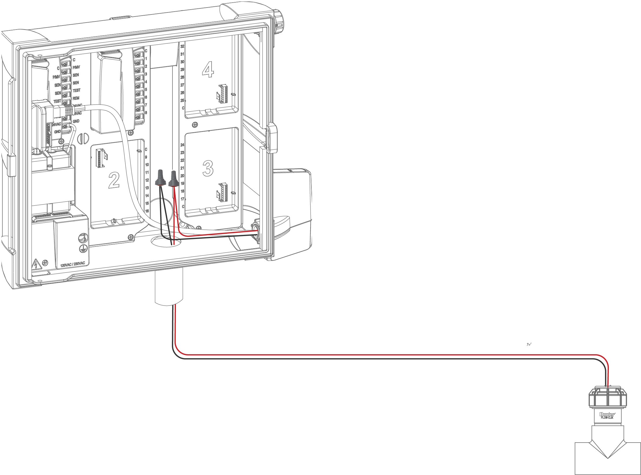
WIFIKIT w/Flow Sensor
- To connect a flow Sensor, route the pair of 18 AWG (1 mm) wires from the sensor into the cabinet (max distance of 1,000 ft.).
- Locate the red and black wires from the communication module.
- Strip the incoming wire a ½" and connect the red/red and black/black using waterproof wire connectors. See the illustration below.
- Complete configuration in the Centralus software. Learn More
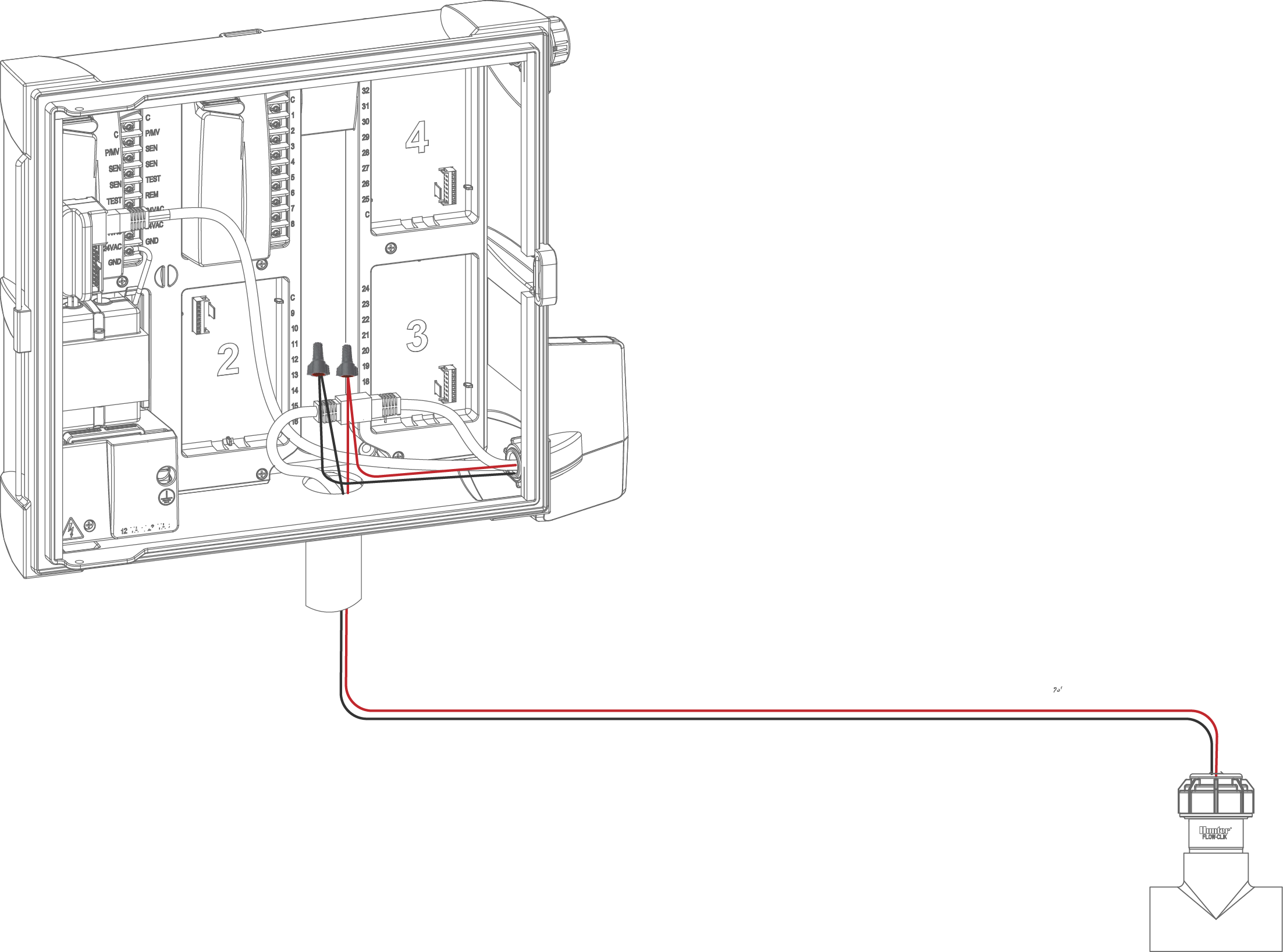
LANKIT w/Flow Sensor
- To connect a flow Sensor, route the pair of 18 AWG (1 mm) wires from the sensor into the cabinet (max distance of 1,000 ft.).
- Locate the red and black wires from the communication module.
- Strip the incoming wire a ½" and connect the red/red and black/black using waterproof wire connectors. See the illustration below.
- Complete configuration in the Centralus software. Learn More
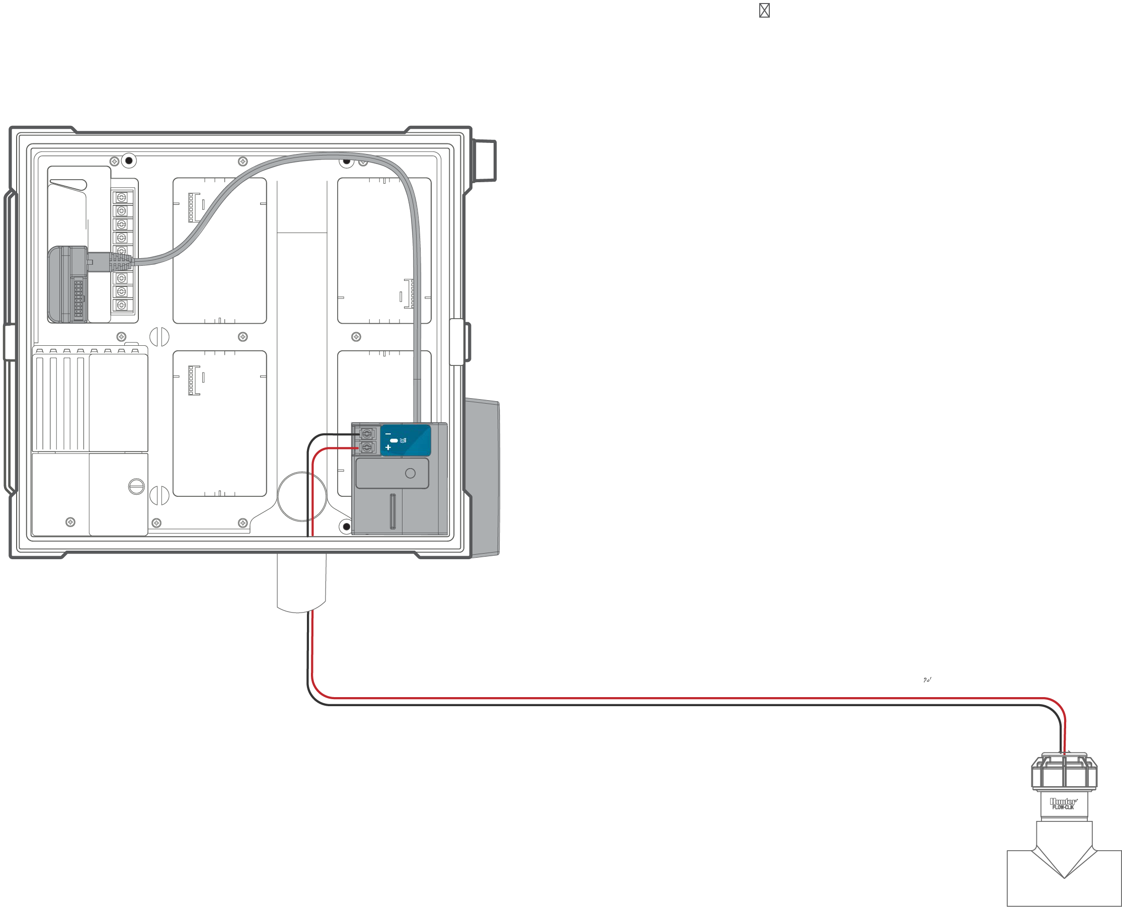
CELL-KIT w/Flow Sensor
- To connect a flow Sensor, route the pair of 18 AWG (1 mm) wires from the sensor into the cabinet (max distance of 1,000 ft.).
- Connect the Red wire to the plus terminal and the Black to the minus terminal. See the illustration below.
- Complete configuration in the Centralus software. Learn More