Flow Sensors allow flow-capable controllers, such as the Hunter ACC2, to monitor actual flow in irrigation systems. With proper setup at the controller, this allows the controller to record and report actual flow in gallons. The recommended Flow-Sync can learn the typical flow for each zone of irrigation and monitor during watering for high and low flow conditions. This equips controllers to respond on their own to incorrect system performance, preventing damage to the landscape and wasted water resources.
- Turn the controller power off before cutting the two-wire path.
- Install shielded 18/2 direct burial wire (recommended red/black colors for troubleshooting purposes). The maximum distance is 1000' using 18G wire.
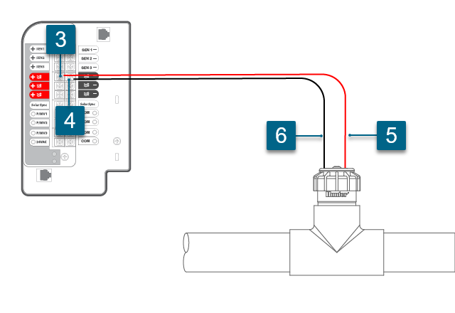
- Connect the red wire from the field cable to 1 RED (+) on the POWER MODULE FLOW TERMINAL.
- Connect the black wire from the field cable to 1 BLACK (-) on the POWER MODULE FLOW TERMINAL.
- Connect RED Flow Sensor wire to the field cable going to 1 RED (+). Seal with included waterproof connectors.
- Connect BLACK Flow Sensor wire to the field cable going to 1 BLACK (-). Seal with included waterproof connectors.
- Turn the controller POWER back on.
- For controller configuration, visit the support section here.
NOTE:The controller has three Flow Sensor inputs built-in, but three more can be added with the A2C-F3 Flow Expansion Module.

This requires a specific model decoder (ICD-SEN) for ACC2 decoder model controllers.
- Program the ICD-SEN address and sensor information with either the ICD-HP, or the programming port on the controller. Learn more
- Turn the controller POWER OFF before cutting the two-wire path.
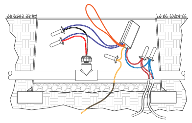
- Cut purple loop as needed for sensor connections.
- Wire PURPLE/WHITE stripe wire to the RED Flow Sensor wire.
- Wire PURPLE wire to the BLACK Flow Sensor wire.
- Allow 5’ (1.5m) slack in wire path at valve box. Cut and strip two-wire path to splice with decoder wires.
- Connect decoder RED and BLUE wires to the red and blue path wires. Seal with included waterproof connectors.
- Turn the controller POWER back on.
- For controller configuration, visit the support section here.
IMPORTANT: Orange loop wire is used for Clik Sensors that do not require a 24VAC source.

Ainda precisa de ajuda? Conte conosco.
Conte-nos que tipo de ajuda você precisa para encontrarmos a melhor solução para você.

