The Cellular Communication Module is used to connect ICC2 Controllers to Hunter’s Centralus™ Irrigation Management Platform. This 4G LTE communication module allows for wide-area connectivity to Centralus cloud-based control and provides an alternative to Wi-Fi and Ethernet connections to the internet.
IMPORTANT: For full compatibility, the ICC2 controller must have a facepack with a date code of 2019 or newer. If not, you will receive a message in the Centralus software to replace it.
A Hunter Centralus account is required to complete the controller configuration. Using an internet-connected smartphone, tablet, or PC, set up a free Centralus Account.
The Cellular Communication Module includes all necessary hardware for plastic, metal, and pedestal ICC2 Controller installations.
- SyncPort Adapter
- Inner Module (SIM card included for activation in North America)
- Inner Module Mounting Bracket for Plastic ICC2 Cabinets
- Shank Nut
- Inner Module Mounting Bracket for Metal ICC2 Cabinets
- Screws (M2.6 x 12 mm; qty. 2)
- External Antenna Adapter for Metal ICC2 Cabinets
- Antenna Housing
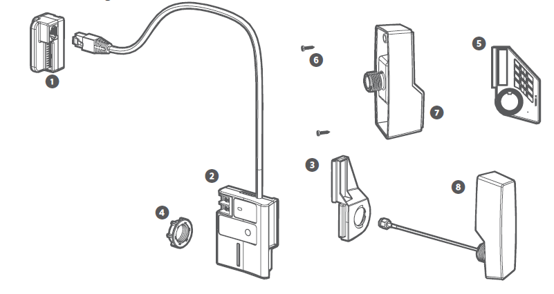
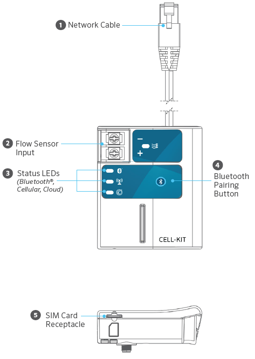
The INNER MODULE is the main component of the Cellular Communication Module Kit. It is powered by the host ICC2 Controller and is installed securely inside the controller enclosure. The magnetic mounting bracket allows for quick installation and removal. The Inner Module connects to an exterior mounted cellular antenna via an SMA connection. It also houses the SIM card required for data activation and provides two screw terminals for a flow sensor input.
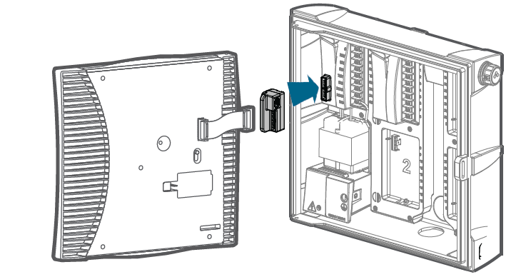
- Turn off AC power to the controller.
- Disconnect the facepack ribbon cable from the Power Module in the upper left corner of the controller.
- Install the SyncPort Adapter onto the Power Module plug.
- Plug the facepack ribbon cable into the SyncPort Adapter.
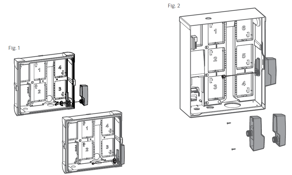
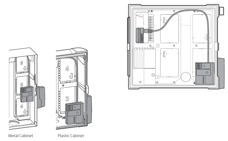
- For plastic ICC2 Controller installations, remove the conduit knockout on the lower right side of the controller cabinet (e.g., Fig.1). For metal ICC2 Controller installations, remove the rubber plug on the right side of the enclosure.
- The Antenna Housing mounts to the exterior of the controller enclosure. Route the coaxial cable through the knockout opening and into the controller enclosure (e.g., Fig.1).
- To secure the Antenna to the cabinet, install the Inner Module Mounting Bracket (for plastic ICC2 Controller installations) over the Antenna Housing thread body and cable, and hand tighten the shank nut to hold both parts in place.
- For metal ICC2 Controller installations, combine the Antenna Housing with the External Antenna Adapter (component #7). Feed the coaxial cable through the adapter and screw the housings
together (see Fig. 2). - Secure the Antenna Housing to the controller using the shank nut and Mounting Bracket for Metal Cabinets.
- Secure the Antenna Housing/Mounting Bracket using the shank nut (for metal cabinets, use the additional mounting bracket).
- Connect the Inner Module to the magnet prior to threading the cable.
- Thread the coaxial cable from the Antenna onto the SMA connector on the back of the Inner Module.
- The Inner Module snaps into place on the Mounting Brackets via magnets.
- Connect the network cable Cat 5/6 plug coming from the top of the Inner Module to the SyncPort Adapter.
- Restore power to the controller to initialize the Cellular Communication Module.
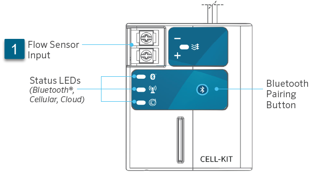
The red and black leads from the Flow sensor are connected to the + (red) and - (black) screw terminals on the communication module (Fig. 1). A minimum wire size of 18-gauge wire can be used to connect the leads from the sensor to the module. For information on installing the sensor in the field, click here.
Still need help? We're here.
Tell us what you need support with and we'll find the best solution for you.

